- INNOVATION TO HELP YOU SUCCEED
Whichever Lucas products you choose, the technology is always the same and guarantees the best possible performance value for money.
Whichever Lucas products you choose, the technology is always the same and guarantees the best possible performance value for money.
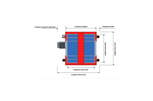
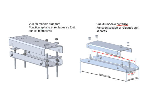
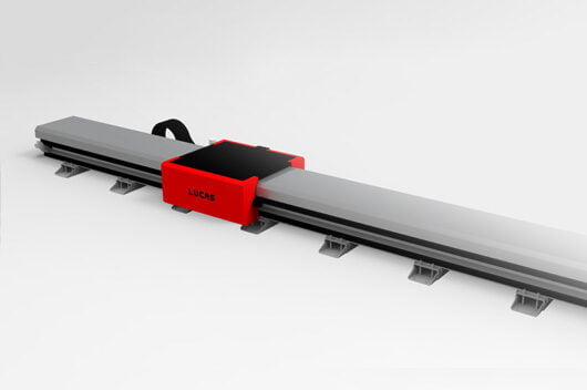
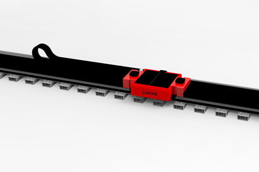
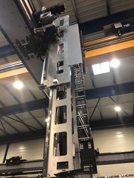
LUCAS carriages are designed so that the maximum possible surface area is usable by the integrator.
All functional transfer elements are either under the carriage or ‘outboard’ (no interaction with the client process).
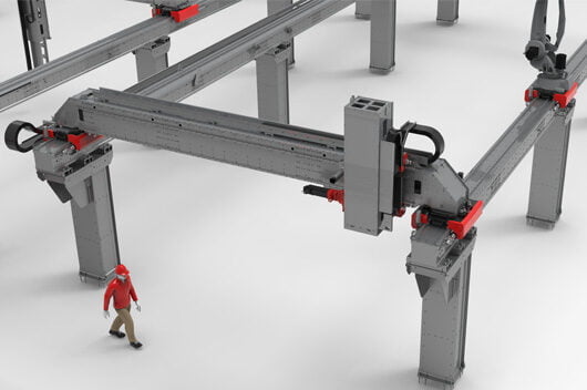
In the case of gantries, there is articulation between the X and Y axes, to make up for geometric faults linked to the plant and remain unaffected by control variations. As standard, our gantries are driven by 2 X motorisations managed as a master/slave model
interested? Contact us
There are two gear precision classes possible on LUCAS axes (see configuration tool) depending on the type of application envisioned (standard or extra precision).
Tooth gap can be adjusted via a mobile plate.
interested? Contact us
As standard, each carriage is equipped with an automatic greasing system (rack, pinion, runner) that is autonomous and adapts to the usage of the equipment. A fault sent to the automation system indicates when to replace the cartridge and/or intervene when the lubrication is not right.
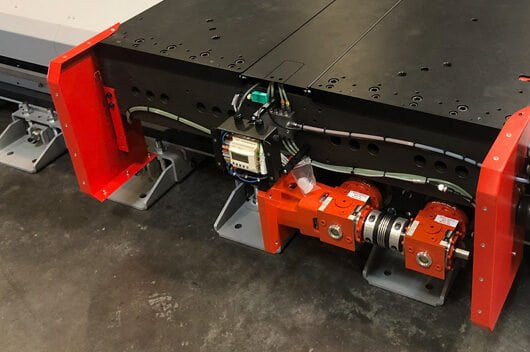
This device also gives real-time information on each axis’s mileage and offers easy maintenance tracking.
interested? Contact us
The beams are made from laser-cut S235 steel assembled by screws, without welding. They therefore offer dimensional stability over time, without annealing.
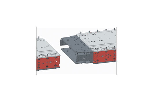
When the product supplied is longer than 13 metres, the beam is delivered in several parts, each measuring a maximum of 12 metres. To facilitate the on-site assembly of the beams, tightening tools are supplied with the beams. A splice system ensures optimum adjustment and precision (see documentation).
interested? Contact us
The Kabelschlepp cable carriers are equipped with cable dividers and aluminium connecting bars. As standard, the links are equipped with a replaceable runner, which reduces the noise from the system.
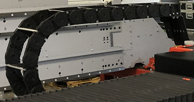
In the event of large sections of chains and/or speeds above 2 m/s, the conduits are covered in a shock-absorbing rubber strip. Two different series are used in the linear axis range: MC, with aluminium stays that can be taken apart, and MT, with aluminium covers for applications in which a closed carrier is required. Depending on the length and the mass, the cable carrier may be gliding or unsupported.
interested? Contact us
Installation on concrete
The area where the linear axis is installed must have clean, floated concrete floors with the minimum requirements detailed below:
Installation on a fabricated steel structure. In some cases, the linear axis cannot be attached directly to the floor, instead being fixed to a special steel structure. The user must ensure the structure is mechanically stable and check its dimensional stability – meaning the absence of vibrations under normal usage conditions (robot acceleration) – and its mechanical strength in emergency stop conditions. Should you require, our design office can provided clarifications regarding load lowering specifications corresponding to the client’s applications.
interested? Contact us
As standard, any straightness error in the direction of movement is adjusted in the factory to be at a value no higher than 0.1 mm/m, so a possible deviation of 1 mm for a 10-metre-long axis. When the application requires a greater degree of straightness, we can provide a special foot that offers a lateral adjustment function.
This foot is installed instead of the standard one, but the rest of the floor anchoring elements are still to be used. However, the straightness must be adjusted before the upper part of the base is tightened completely.
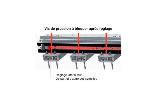
Once the axis is level and before tightening, the straightness must be adjusted via the M36 screws on either side of the feet. The best procedure to follow is the same as the level adjustment procedure: adjusting the areas with the biggest error. With experience and plenty of time, a target value of 0.02 mm/m can be achieved.
interested? Contact us
For activities that require a high degree of rigidity, the number of bases or pillars can be increased to limit any flexion or torsion in the beams.
interested? Contact us
PVC or Kevlar bellows can be provided for all LUCAS axes, depending on your application. The LUCAS configuration tool can automatically calculate the excess length generated by the addition of this accessory.
interested? Contact us
On ALSP models, the enclosed face is walkable, meaning the operator can walk on the axis easily.
This enclosure protects the mechanism from external aggressions (powder, paint overspray, oil dripping, residue, etc.).
interested? Contact us
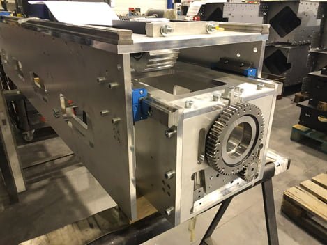
There are 2 possible backlash compensation systems on LUCAS axes:
Electric backlash compensation system
Two standard gears are installed on the same carriage. The control cabinet then manages a dynamic precharge to use the gears to compensate for the backlash in the rack and pinion assembly.
Mechanical backlash compensation
Through a defined precharge, a REDEX double-pinion gear compensates for the backlash in the rack and pinion assembly,
A linear scale may be added for direct coding on the linear axis.
interested? Contact us
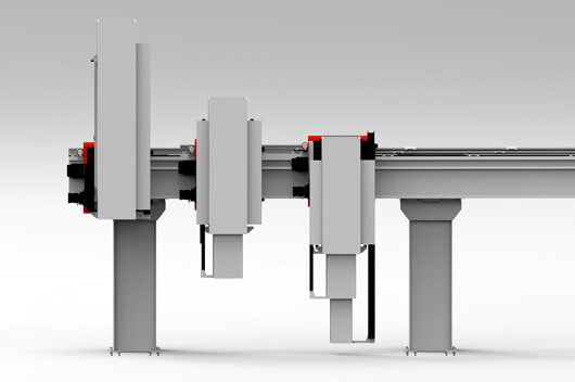
Arms from 300 to 3 000 kg
The Lucas Z arm system is based on 4 sizes of extendible Z arm, which can be used to make simple arms, bi-telescopic arms or even tri-telescopic arms.
Thanks to the Lucas configuration system, you can find out which arm combination you need according to your ceiling height.
All Z arms can carry a rotary axis on the end, thus transforming a 3-axis robot into a 4-axis one.
Z arms are made from 2017A aluminium sheets, assembled with screws, like the beams.
All the gears are planetary with backlash of < 3 arcmin on 1 stage and < 5 arcmin on 2 stages. On the vertical axes, there is an additional safety brake provided, to be installed between the gear and the motor of your equipment. It can double braking and secure hold functions in the event of maintenance.
A rotation can be added to the end of the Z arm with a hollow arm system, so that client process cables can be passed through.
interested? Contact us